Article
How to Retrofit a Legacy Bioreactor to OPC-UA and MQTT with QB Control
By QB Systems · 6 min read
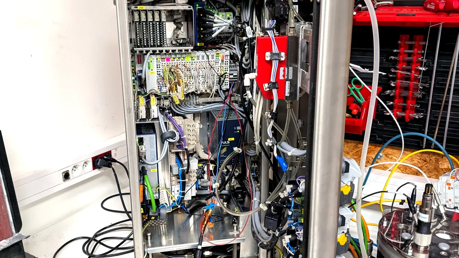
You have a working bioreactor and modern digital probes, but their data still lives on the vessel. Getting pH, DO, temperature, and the rest into an OPC-UA and MQTT namespace usually means a transmitter, a converter, a gateway, and a PLC in between. This guide walks through putting that same vessel on a modern data layer with QB Control, keeping the bioreactor you already own. It is written for a process or automation engineer, and the core wiring is a day’s work.
Before you start
- The bioreactor and its probes, mounted and calibrated as you run them today.
- The probe interfaces to hand. QB Multisensor reads Hamilton and Mettler-Toledo digital sensors over RS-485 Modbus, Pt100 through a converter, and the A4BEE optical foam and level sensor. Note which of yours are digital and which are analog.
- A QB Edge controller and at least one QB Multisensor module.
- A network drop for QB Edge (Ethernet), or Wi-Fi or LTE if a cable is impractical.
- The name of the OPC-UA or MQTT endpoint your plant historian or SCADA expects to read.
Step 1: Inventory the instruments and their interfaces
List every signal on the vessel and how it speaks: pH, dissolved oxygen, temperature, conductivity, dissolved CO2, redox, plus pumps and any foam or level sensor. Mark each one digital (RS-485 Modbus, or a vendor link) or analog (Pt100, 4-20 mA). This tells you how many QB Multisensor channels you need and where a converter is required. One QB Multisensor carries up to six sensors on a single Power-over-Ethernet cable, so most single-vessel setups need one module.
Done when every signal on the vessel has a row and a known interface.
Step 2: Mount QB Edge and the QB Multisensor
Fix QB Edge near the vessel and connect a QB Multisensor to one of its seven LAN PoE ports. Power and data share the one cable, so there is no separate supply to run. Connect QB Edge to the plant network over Ethernet, or bring up Wi-Fi or LTE if a drop is not available; a WireGuard VPN is there when you need remote access later.
Done when QB Edge has power and a network address, and the Multisensor’s link light is up.
Step 3: Connect the probes and let QB Edge discover the module
Terminate each probe on the QB Multisensor. QB Edge auto-discovers the module on connection, so there is no manual commissioning of the box itself. For Hamilton and Mettler-Toledo probes, use the RS-485 Modbus inputs; for a Pt100, route it through the converter; wire the A4BEE optical sensor to its dedicated input.
Done when the module and its attached probes appear automatically in QB Edge.
Step 4: Bring up QB Control and name the channels
Open QB Control in a browser. It is a SCADA-class platform that runs in the browser on any operating system, so there is nothing to install on an operator’s machine. Name each channel in plain language, set units, and confirm the process value and status for every probe. QB Control generates the P&ID dynamically as you add signals, so the diagram reflects the vessel without hand-drawing it.
Done when all six process values read live and correctly named in one interface.
Step 5: Apply pre-built service templates instead of coding loops
Rather than hand-code a PID loop for each variable, apply the matching QB Control service. The catalog carries 37 pre-built services across ten categories: pH, dissolved oxygen, temperature, feed, aeration, sampling, gravimetric feeding, perfusion, and more. Pick the service, point it at the right channel and actuator, and set your thresholds. Because the services are configurable and pre-tested rather than custom code, this is where a retrofit stays a configuration job instead of a programming project.
Done when your control strategies run from services, with alarms set on each.
Step 6: Publish to your plant over OPC-UA and MQTT
Expose the vessel to the plant data layer. QB Control publishes every reading and its status natively over OPC-UA, MQTT, and Modbus, so there is no separate bridge to build and validate for each protocol. Point your historian or SCADA at the QB Control OPC-UA server, or subscribe your broker to the MQTT topics, and confirm both process value and quality arrive on the other side.
Done when your historian or SCADA reads the vessel’s data over your chosen protocol.
Step 7: Turn on compliance: audit trail, access, and alarms
Enable the 21 CFR Part 11 audit trail and role-based access control, both included in QB Control. Configure alarms to ISA-18.2 so priorities, shelving, and states behave the way a regulated floor expects. Electronic signatures are on the roadmap rather than shipping today, so scope any signature-dependent workflow around that.
Done when every parameter, recipe, and user action is logged, and alarms are configured and tested.
Step 8: Validate as a configured system
Validate the retrofit as GAMP 5 Category 4 (configurable, pre-tested software) rather than the Category 5 custom-code path a hand-built integration would force. That is the difference between qualifying a configured system and qualifying bespoke code, and it is where most of the calendar savings on a retrofit actually come from.
Done when your IQ/OQ/PQ covers the configured services and the data path end to end.
Common pitfalls
- Mixed-vendor addressing. On a shared RS-485 bus, give each Modbus device a unique address before you connect it, or two probes will fight for the same slot.
- Assuming MQTT needs a separate bridge. It does not here: QB Control is MQTT-native. Do not budget a gateway you will not build.
- Skipping the inventory. A probe you forgot in Step 1 is a converter you did not order. Finish the inventory before you mount anything.
- Rip-and-replace instinct. The point of a retrofit is to keep the vessel. If a plan starts by replacing working hardware, it is no longer a retrofit.
Checklist
- Every signal inventoried with its interface
- QB Edge mounted, networked, and powered
- QB Multisensor connected and auto-discovered
- All channels named and reading live in QB Control
- Control strategies running from pre-built services, with alarms
- Data published over OPC-UA and MQTT and confirmed downstream
- 21 CFR Part 11 audit trail, RBAC, and ISA-18.2 alarms on
- Validated as GAMP 5 Category 4
Where to go next
For the business case behind a retrofit, with a real CDMO project and the trade-offs against Sartorius MFCS 4, read A Second Life for Your Sartorius Bioreactors. To choose between taking over control with a retrofitted PLC or running read-only alongside your existing PLC, see Retrofitting deployments.
If you are weighing this against a full DCS or a transmitter-and-gateway build, the QB Control vs the incumbents comparisons put the effort and cost side by side. The multi-sensor architecture whitepaper models where the integration hours actually go.